Weather Station – Receiver

I had written about my weatherstation, why I use Xbee rather than WiFi and and a few posts about sensors and placement.  The last remaining topic is to talk about receiving / displaying the data and sending it to the internet.

This receiver / basestation / coordinator has been the ugliest component of the build, likely because I wanted it to do too much. It is supposed to be an actual weatherstation with interactive display, a clock and my central hub for my XBee network.  While it has been a useful exercise in learning how to program wildly different requirements it quickly exceeded what an Arduino Uno can do.  I had to move to an Arduino Mega (knockoff from Aliexpress, by the way, works great) which in turn meant that the Sparkfun WiFi shield doesn’t work anymore.

The entire assembly is an unholy mess of wires and connectors.
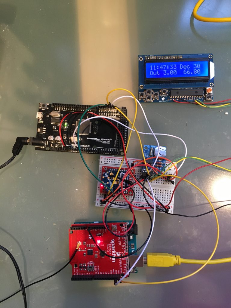
Ugly but it works (Kind of)

Components:

  • Top right: Standard LCD Display with shield allowing me to communicate with I2C (about that later)
  • Left: Arduino Mega, Aliexpress knockoff.  This is the Coordinator
  • Middle: breadboard with XBee (in coordinator mode), real time clock (top) and a TMP36 analog temperature sensor.
  • Bottom:  Arduino Uno with a WiFi Shield connected by I2C to the Coordinator Arduino.   I added an external antenna to the shield(black lead left side of image)

How it works

The Xbee Weatherstation sends data every 30 seconds from its position on the roof.  The Coordinator receives the data, displays it on the LCD shield and sends it via I2C to the connected Arduino Uno.  The Uno is connected via its WiFi shield to ThingSpeak and sends it the data as it comes in.  The Thingspeak data is embedded into this blog.

The code is here:  Mega (Coordinator) and WiFi Conector (Uno) and most of it is pretty straight forward but inelegant.  Especially the coordinator “grew” in scope over time but it has been pretty stable, so I left it.  The Arduino Mega still has plenty of memory and ports left so there is no real reason to tighten the design =re-write).  If it ain’t broke and all that.  The LCD shield has shown to be very limiting.  I wanted to show the time derived from real time clock as well as the current weather conditions with in/outdoor temperature, outdoor humidity, wind speed, wind direction, gusts rain rate, I just had too many numbers to display at any time.  I personally can not stand displays that automatically scroll through values and hence I enabled the buttons on the shield to switch between the states.  Up Button now shows the outdoor temperature and humidity.  Right Button the indoor temperature of the TMP36 (which by the way is frequently reporting -100 C data, likely bad connection).  Button Down is Barometric pressure, Button Left is Wind Speed, gusts and directions in degrees (need to make lookup table for actual compass rose values).  The “Select Button” switches the display to Rain Rate.

The Mega uses I2C to communicate with the LCD shield as well as the Real Time Clock and hence has to serve as master for the devices.  I2C is a pretty elegant protocol as it enables communication with only two wires (and ground) but I found it hard to learn until I found the I2CAnything library from Nick Gammon (thank you!).  I have to send float values across the I2C bus and doing this without the library exceeded my programming skills.  I2C also allowed me a pretty straight forward connection to the Arduino Uno whose sole purpose is to drive the WiFi shield.  The Uno is in “slave mode” and waits for data to be sent to it, the sends it to my Thingspeak channel.

Aside from being badly soldered (LCD shield), being a mess on a breadboard (everything else), expensive (2 arduinos,1 WiFi shield) and using a TMP36 which gives me issues its working perfectly!

To clean up, I bought an Adafruit Huzzahh ESP8266 breakout board, the promise is / was that it is a fully-fledged Arduino with integrated WiFi, it just has fewer ports. The goal was to connect it to the Mega and scrap the Uno / WiFi shield to make the entire package cheaper and more transportable. Turns out the ESP8266 is well documented and can be used as a I2C master but does not currently work as a slave.  This is a problem since I can not see myself re-writing the entire code for the Mega and allow the ESP8266 as a Master.  Apparently, there are tricks to use systems with 2 masters but this is getting unwieldy.  I could send the data by serial port (the Mega of course has many serial ports left) but as stated above, reliably sending floats is something I yet have to learn.


For now, I decided to live with the system but pack it into a more self contained box, use actual boards and soldered connections rather than the breadboard and stick it into a box that hides the mess.  I will also need to clean up some code (wind direction as actual compass directions for example and find a system to set the clock manually, I didn’t appreciate just how much the RTC drifts over time).  After that, I will focus on other projects and eventually move the entire coordinator / display into a PC (I have an old Linux laptop somewhere) and was itching to learn how to use “Processing” anyway).

Weather station: Sensor Package

I explained why I am building a weather station and where I intended to place it.  I realized that my writing is “narrative” and not instructive and from now on, I will try to be more concise and separate my posts into “why” and “how”.

Sensor Package

Why: I discussed the design requirements in the previous post, so I keep this short.  The requirement was for a robust, powered but wireless sensor package that survives environmental challenges for years and accurately reflects its micro climate.  The system is also based on a single Arduino Uno because I am not (yet) at the stage to program the ATmega328P directly.  This was is my first Arduino project, so the process of getting it done is very slow and my code is sloppy, badly annotated and inefficient.  But it works, don’t hate me.

Pretty early I had to decide how I wanted to structure the communication.  Since I was building a XBee network with mesh capability (about that later), I did not want to go into “streaming” mode, its too slow, too unreliable and in the end overkill. The proper way of doing these networks is “beacon-based” where a central station (coordinator) requests a data package.  While this is the right way of doing it, duplex communication over Xbee was a bit too much for me as first project and I put the timer on the sensor package. For the sampling interval, I now chose 30 seconds which I will reduce as soon as more sensors occupy my network.  For this season however, this is fine.

How:  Hardware:  Arduino Uno, DHT-22, BMP180, XBee Radio, and the Sparkfun Weather Meters.  Scraps of duct tape and double-sided tape to keep items from shifting inside the junction box.  Various cables and generic connectors.

Code  All code is in GitHub in this project.

General comment on code: I am not a programmer and the code evolved over a few months worth of trial and error. I am sure it can be improved and streamlined and in the end I will likely do so.  For example, I rely heavily on global variables and floats, a very bad practice on Arduinos.  For now it works.

The DHT22 is connected to Digital Pin 4 and uses a standard library. I trimmed down one of the examples and it generates temperature and humidity data as soon as its function is called.  Its pretty easy and I stick with Celsius since I can’t get my head around Fahrenheit.

The BMP180 pressure sensor is defined as an object and I (full disclosure) I am not entirely clear on what the code does.  The code has many redundant checks whether the sensor properly initialized or not but I don’t use any of them in subsequent communication.  I will revisit this sensor next year, for now it gives me reliable data.

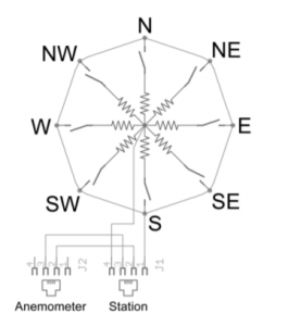
The Windvane was the one device that looked the most complicated but turned out to be very straight forward.  It relies on a series of resistors to generate 16 distinct voltages depending where its pointing toward (datasheet).  This in turn means that it can rely on a single analog pin (quite ingenious).

wind-rose
Diagram from Datasheet

The code uses 2 arrays, the first are the nominal values that we expect from the resister/voltage output.  The second array is the associated wind direction in degrees. The measured analog value (vaneReading) is sequentially compared against the values of the first array and the value with the smallest difference is chosen. The corresponding array position is then looked up in the second array which holds the wind directions. This should allow for some fluctuations of the sensor reading (temperature for example).


void windRose()
{
  vaneReading = analogRead(VANE_PIN); //read the analog signal from the Windvane, optional: float voltage= vaneReading * (5.0 / 1023.0);

  for (n = 0; n < 16; n++) //16 possible positions of the windvane
  {
    diff = vaneReading - pgm_read_word(&vaneValues[n]); // calculate the difference between the actual reading and the ideal valuye from the array
    diff = abs(diff);

    if (diff < allDiff) { //select the vaneValue with the smallest difference to the ideal. The vaneReading is a little noisy, this seems to take care of it
      allDiff = diff; //allDiff = smallest difference from the array compoarison.  Kind on bubblesort.  dont really need this value, for debugging
      allN = n; //allN is the position in the array with the smallest different between ideal and measured
    }
  }

  windDirection = (pgm_read_word(&vaneDirections[allN]) / 10); //report winddirection
  
  diff = 1000;  //set diff to something high so that the routine doesnt get stuck
  allDiff = 1000;
}

}

The rain sensor and anemometer work differently, they rely on interrupts to trigger counters. Arduino Unos have 2 interrupt pins (Pin 2 = Interrupt 0 and Pin 3 = Interrupt 1) and programming them is pretty straight forward. The math however is a little different since the interrupts are counted during the interval time, by definition they are averages,  “interrupt counts / interval time”. For wind speed, it turned out that the interval time is too long, the values are all smoothed out. Hence I added another timer to measure gusts.  For the code itself, I relied heavily on Kevin Kessler’s blog post installing the exact same sensor package.  His programming skills far exceed mine and for good code, go there.

As a (unnecessary?) safety precaution, I turn the interrupts off during the assembly and transmission function.  I’ll cover the XBee transmission in my next post.

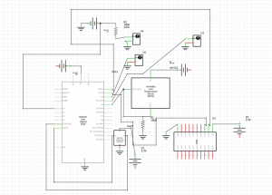
Below the Fritzing Schematic.  I likely made mistakes in the wiring, first time working with formal layout programs.


sensor-package

Interacting with the world

Alright, so lets do this blog thing.

I recently decided that I needed to stretch my brain to prevent myself falling off the evolutionary ladder and becoming the world’s largest broccoli.  Others may call it a midlife crisis, I call it a hobby but the concept is the same – I wanted to create something and learn new (maybe even useful!) skills to ward off depression and boredom at work.

Real engineers won’t use the Arduino platform of course, its a toy to them.  I on the other hand, have no such pride and eagerly read up all the things about the devices and the community, culminating to purchase a Sparki Robot for myself for Christmas (on sale).

Sparki is a delight and works right out of the box.   I drove it around a little and started to get used to the IDE when I decided that it is a little too “pre-fabricated” for me.  I wanted to learn to build these things, not just use them.  There is nothing wrong with the robot itself (I have it and I am looking forward to re-activate it) but I went and bough an Arduino Starterpack containing an Uno, some resistors and a great project book.  I faithfully followed most examples until I understood the principle and started messing with the code or hardware until things broke.  Subsequently, I added Simon Monk’s excellent book to my reading list, a lot more background on the programming language.

And with knowledge, my aspirations grew and I looked for a big project that would be useful, achievable and yet pretty complex.  Coincidentally, I was getting interested in building a chicken coop for no practical reasons whatsoever other than it’ll be a cool thing to do, I like eggs, chicken breast pretty and much all non-stinging critters.  However, chickens require a ton of maintenance and care.  Starting from a coop from scratch (sorry) is a tad daunting.

However, if one combines an Arduino with a chicken coop one could envisage a system where a lot of the routine maintenance and care is automated!

A project was hatched (sorry).  I would build a chicken coop where all environmental monitoring and as many of the routine jobs as possible would be taken care of by automated systems.  People have done this and everything that has been done before, can be improved on.

Ok, now we are getting somewhere.  The Arduino project has a purpose.  So, I structured the project into:

  1. Data acquisition (power supplies, sensors, temperature, humidity, light levels etc)
  2. Data processing (averaging, outlier removal, smoothing)
  3. Data transmission (need to go wireless, we have 3 acres)
  4. Data display and analysis (cloud or local)
  5. Action (opening of gates, vents (sorry), heating elements, water pumps etc).
  6. Get chickens

So looking at this list, I decided to start at the top and learn all about Arduino’s ability to acquire environmental data, process it and transmit it to some jury-rigged base station. Without chickens however, I would need a test bed to practice my skills and I quickly decided that a weather station would be ideal.  First of all, its useful (nearly as useful as looking out of the window), secondly it would be an exact copy of a wireless environmental sensory platform that I would later be using (temperature, humidity for example).

Now, the world does not need more weatherstation designs.  Even with Arduinos, there are hundreds, I assume everyone who ever bought an Arduino puts a DHT22 temperature and humidity probe on it at some point and displays the data with an LCD shield.  New, this isn’t.  For me, it was motivating because I could test my skills and designs without harming any chickens.

And so, the build of my weatherstation began.

Of which I shall write in subsequent posts.